
TL;DR
- Backup jobs exit clean while recovery fails. If the VPC, IAM roles, or security groups in the recovery workspace drifted from production, the application won't start regardless of what the backup metrics show.
- Not every service needs the same recovery architecture. A payment flow needs cross-region replication and automated failover. An internal wiki needs a snapshot and a runbook. Conflating the two wastes budget or breaches SLAs.
- If rebuilding the network or IAM roles during an incident requires manual work, the RTO is unpredictable; manual reconstruction at 2 AM under incident pressure always takes longer than the target.
- Firefly snapshots full cloud environments, including networking, IAM, configurations, and dependencies, as deployment-ready IaC, then continuously checks that recovery workspaces reflect what production actually runs. Gaps surface on a dashboard, not during a failover at 3 AM.
- DR plans that aren't tested on a schedule aren't plans, they're hypotheses. Measure achieved RTO and RPO after every drill and fix deviations before the next one.
Cloud environments fail in ways that backup tools were never designed to handle. A regional outage takes down every service running in us-east-1, including the recovery tooling. A ransomware attack encrypts snapshots stored in the same account as the production environment. A Kubernetes node group disappears, and the Terraform state that defined it has drifted three months behind the live configuration. In each of these cases, a successful nightly backup is irrelevant because the failure is not a missing file; it is a missing infrastructure state.
Disaster recovery in cloud-native environments is an operational engineering discipline. It requires recreating networking, IAM policies, Kubernetes resources, DNS records, and service dependencies, not just restoring data. Teams that treat DR as a backup schedule will discover this gap during a real incident, under time pressure, when the cost of discovery is highest.
This guide covers the specific practices that infrastructure and platform teams need to build recovery strategies that hold under real failure conditions.
11 Cloud DR Best Practices for Infrastructure, Dependencies, and Automated Failover
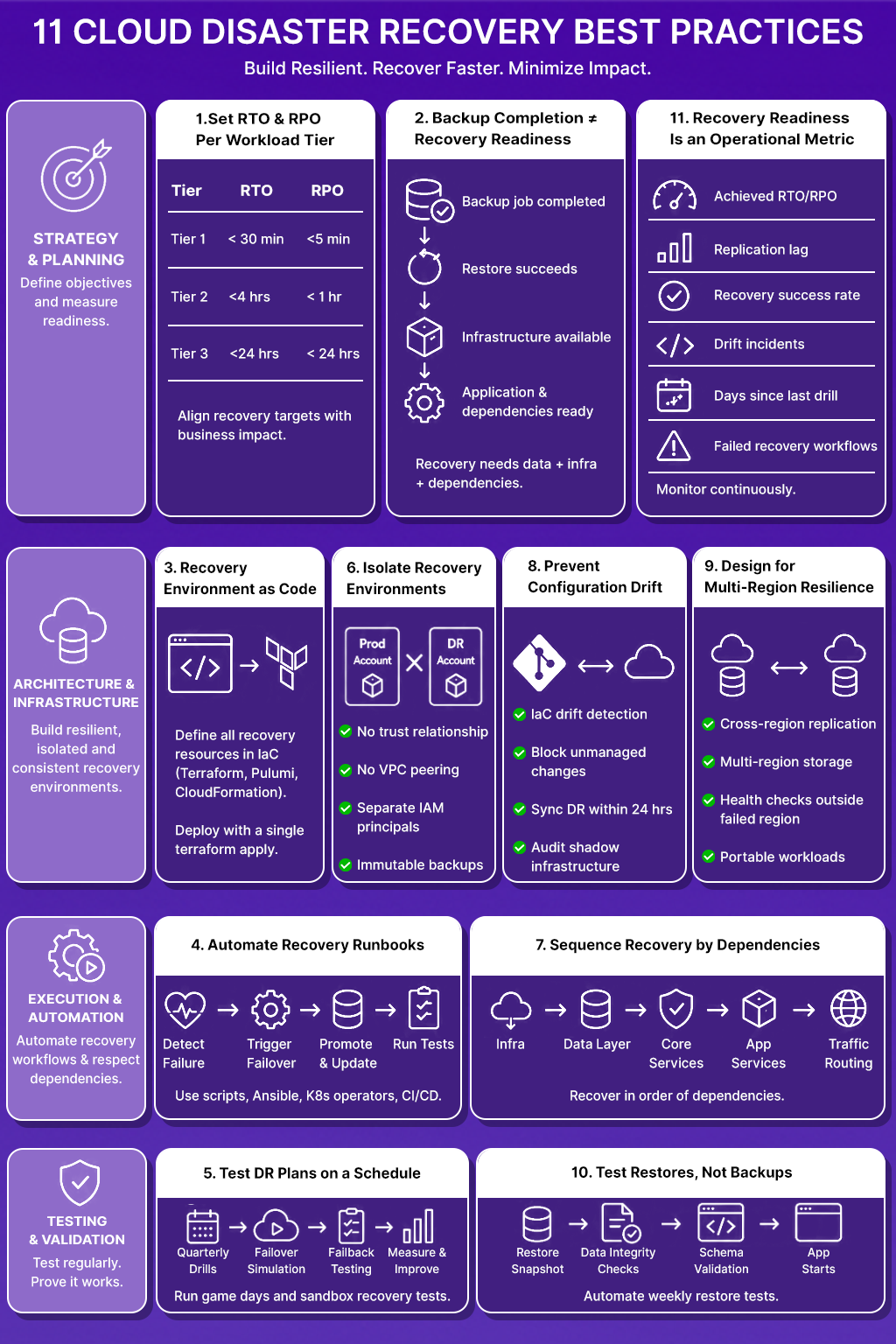
Recovery fails at the infrastructure layer, the dependency layer, and the process layer, not just the backup layer. These eleven practices address all three.
1. Set RTO and RPO Targets Per Workload Tier, Not Per Organization
A payment processing service and an internal analytics dashboard do not share recovery requirements. Treating them identically wastes money on one and under-protects the other.
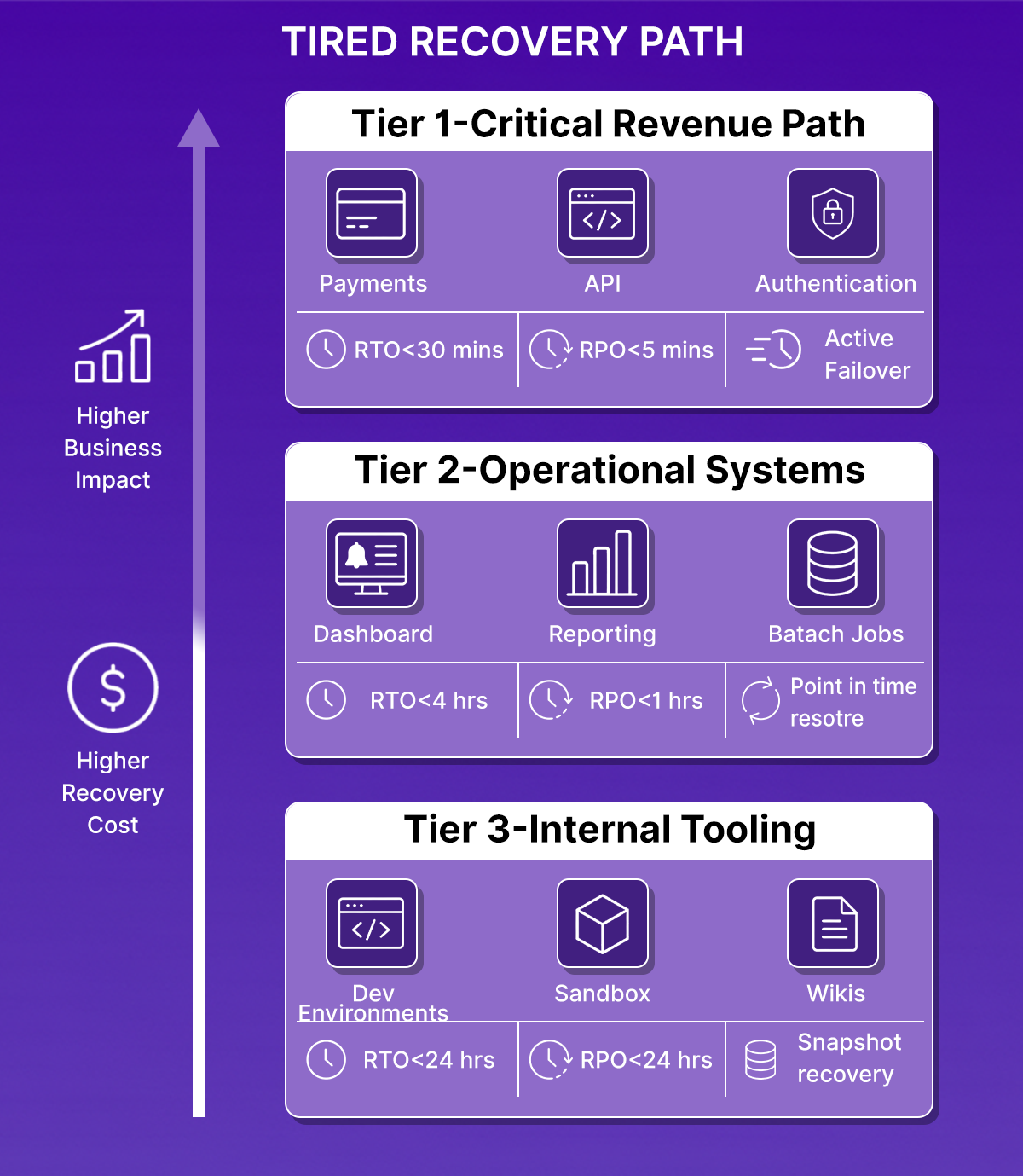
Classify workloads into three tiers based on customer impact and revenue exposure:
- Tier 1, Customer-facing revenue path: Payment flows, authentication, core API. RTO under 30 minutes. RPO under 5 minutes. Requires active-active or active-passive replication with automated failover.
- Tier 2 Operational but not revenue-critical: Internal dashboards, batch jobs, reporting pipelines. RTO under 4 hours. RPO under 1 hour. Point-in-time restore with pre-validated recovery playbooks.
- Tier 3, Non-critical internal tooling: Dev environments, internal wikis, sandbox accounts. RTO under 24 hours. RPO under 24 hours. Snapshot restore with manual runbooks.
The cost difference between Tier 1 and Tier 3 architectures is significant. Active cross-region replication for a Tier 3 Postgres instance incurs infrastructure costs without a corresponding business justification. Setting unrealistic RTO targets for Tier 3 services also creates operational debt; teams spend time maintaining recovery infrastructure for workloads that do not justify the investment.
Define these tiers in a service catalog and tie them to SLAs. When a new service is deployed, it inherits a tier assignment and a corresponding recovery architecture. Those tier-to-architecture mappings, warm standby for Tier 1, pilot light for Tier 2, backup and restore for Tier 3, are the same strategy choices platform teams work through when building a DR plan from scratch; see our guide to cloud disaster recovery for how that decision plays out end to end.
2. Backup Completion and Recovery Readiness Are Not the Same Metric
A backup job that exists with status 0 confirms that data was written to storage. It does not confirm that the data can be restored, that the target environment exists to receive the restore, or that the application will start after the restore completes.
Backup and DR address different failure modes:
The most common DR failure pattern: the backup restore succeeds, but the application fails to start because a dependent service, a secrets manager entry, a DNS record, or an internal API endpoint does not exist in the recovery account. The root cause is not the backup. It is the absence of dependency mapping in the recovery plan.
Every DR strategy needs both components: a data recovery path and an infrastructure recovery path. Neither one alone is sufficient.
3. Recovery Environments Must Be Defined in Code, Not Rebuilt from Memory
When a production region goes down, the team responsible for recovery should not be writing Terraform modules, recreating VPC CIDR blocks from documentation, or manually recreating IAM roles. If that is the recovery process, the RTO is, however long those tasks take, which is unpredictable and error-prone under incident pressure.
Every resource required for recovery must exist in version-controlled infrastructure code:
- VPC configuration, subnets, route tables, security groups
- IAM roles, policies, and service account bindings
- Kubernetes cluster configuration, node groups, namespaces, RBAC
- DNS zones and records
- Secrets manager structure (not secrets values, the structure and access policies)
- Load balancers, certificate ARNs, and ingress configuration
Tools: Terraform, Pulumi, or CloudFormation. The choice of tool matters less than the discipline of treating recovery infrastructure as a first-class code artifact, reviewed, tested, and applied through a CI/CD pipeline.
A recovery environment should be deployable from a single terraform apply targeting the recovery workspace. If it requires manual steps, those steps are gaps in the recovery plan.
4. Manual Recovery Runbooks Fail Under Incident Pressure
A 40-step Confluence page is not a disaster recovery procedure. It is a description of what someone did once during a drill, documented after the fact, and never validated against a real failure scenario. Under an actual incident, a pager going off at 2 AM, partial information, team members joining from different time zones, and manual runbooks introduce execution errors that extend downtime.
Recovery workflows should be automated:
- Automated failover: DNS failover, load balancer target group switching, database promotion from replica to primary; these should trigger on health check failure, not on a human completing a checklist.
- Recovery runbooks as code: Shell scripts, Ansible playbooks, or Kubernetes operators that execute recovery sequences deterministically. Each step is a function call, not a human action.
- CI/CD-driven recovery validation: After a failover completes, a pipeline runs smoke tests against the recovery environment, checking that the application returns expected HTTP responses, that database connections are healthy, and that dependent services are reachable.
- Failback automation: The process of returning traffic to the primary region after an incident should be as automated as the initial failover. Manual failback is a second failure window.
Platforms like Firefly provide visibility into infrastructure state during failover, helping teams confirm that the recovery environment reflects the expected configuration before traffic is shifted.
5. DR Plans That Are Not Tested on a Schedule Should Be Treated as Untested
Recovery testing must be scheduled, executed, and measured:
- Quarterly DR drills: Full failover simulation for Tier 1 services. Measure achieved RTO and RPO against targets. Record every deviation and track remediation.
- Failover simulations: Simulate a regional failure by re-routing traffic to the recovery environment. Validate that all dependent services resolve correctly in the recovery region.
- Failback testing: After every failover test, run a failback test. The return path breaks as often as the forward path.
- Sandbox recovery validation: For teams that cannot afford production disruption during drills, a parallel environment that mirrors production infrastructure allows testing restore procedures without customer impact.
- Game days: Structured exercises where the team responds to a simulated incident using only documented recovery procedures. Game days surface gaps in runbooks faster than reviewing documentation.
Drill results should feed back into the recovery plan. If a quarterly drill reveals that the RDS restore takes 45 minutes against a 30-minute RTO target, that is not a note for the post-mortem; it is a design defect that requires a fix before the next quarter.
6. Recovery Environments Sharing Infrastructure with Production: Extend the Blast Radius
A ransomware attack that encrypts production storage will also encrypt recovery snapshots stored in the same AWS account. An IAM misconfiguration that allows lateral movement through production will allow the same movement through a recovery VPC in the same account. Recovery infrastructure co-located with production does not reduce recovery risk; it inherits production's risk surface.
Recovery environments require isolation at multiple levels:
- Separate AWS accounts or GCP projects: The recovery account should have no trust relationship with the production account except for a tightly scoped cross-account IAM role used for replication.
- Isolated VPCs: No VPC peering between production and recovery. Recovery traffic should not be routable from production except through defined replication paths.
- Segmented IAM boundaries: The IAM principals that operate production should not have permissions in the recovery account. Recovery operations should use a separate set of credentials.
- Immutable backup storage: Recovery snapshots should be written to storage where production workloads cannot delete or overwrite them. AWS S3 Object Lock or GCS retention policies prevent ransomware from reaching backup data through the production account.
Isolation also enables non-disruptive DR testing. A recovery environment in a separate account can be provisioned, tested, and torn down without any risk to production traffic. That isolation logic gets more complex once recovery spans providers instead of just accounts, our guide to automated multi-cloud DR planning covers how to keep AWS, Azure, and GCP backups in sync without each cloud's tooling becoming its own blind spot.
7. Applications Fail to Recover Because Dependencies Are Not Sequenced
A microservices application does not start in isolation. The authentication service needs the user database to be writable. The API gateway needs the authentication service to be healthy before it processes requests. The notification service needs the message queue to exist before it can publish events. Restoring each service independently, in arbitrary order, produces a partially started application where health checks fail because upstream dependencies are not ready.
Recovery sequencing must reflect the actual dependency graph:
- Shared infrastructure first: VPC, DNS, IAM roles, secrets manager
- Data layer: Databases promoted from replica, object storage policies applied
- Core platform services: Service mesh, ingress controller, certificate provisioning
- Shared application services: Authentication, authorization, feature flags
- Dependent application services: Services that consume the shared layer
- Traffic routing: DNS records updated, load balancer targets switched
Document the dependency graph for each application tier. Tools like service mesh dashboards or APM dependency maps surface undocumented service-to-service calls that belong in the recovery sequence but are not in any runbook.
Recovery failures caused by undocumented dependencies are preventable. The dependency is always present in production; it just wasn't documented.
8. DR Environments Drift Away from Production When Configuration Changes Are Not Tracked
A team adds a new database subnet to production in January. The recovery environment Terraform module is not updated. In March, a DR drill fails because the application cannot resolve the database hostname in the recovery region, as the subnet was never replicated. The backup is intact. The infrastructure is wrong.
Cloud environments change continuously: new resources are provisioned outside of IaC, security group rules are modified through the console, and Kubernetes configs are patched in-place. Every untracked change is a gap between production and the recovery environment.
Practices that keep recovery environments current:
- IaC drift detection: Run Terraform plan against production and recovery environments on a schedule. Any difference between the plan and live state is a drift incident.
- Prevent unmanaged changes: AWS Config rules or OPA policies that flag resources created outside of Terraform prevent drift from accumulating. Resources that exist in AWS but not in the Terraform state cannot be replicated for recovery.
- Recovery environment refresh cadence: Apply production IaC changes to the recovery workspace within 24 hours of merge. Treat recovery environment lag as a known risk with an expiry.
- Shadow infrastructure audit: Periodically audit the recovery account for resources that have no corresponding Terraform resource. These are recovery gaps.
Firefly provides continuous visibility into cloud asset changes and infrastructure drift, allowing teams to detect when production configuration changes have not propagated to recovery environments before a drill or a real incident surfaces the gap.
9. Single-Region Architectures Fail When the Region Fails
AWS us-east-1 outages affect every service running in that region, including Route 53 health checks that are supposed to trigger failover. A recovery architecture that depends on an orchestration layer running in the same region as the failure cannot execute failover when the failure occurs.
Recovery architectures must eliminate regional single points of failure:
- Cross-region database replication: RDS read replicas in a secondary region are promoted to primary on failover. Aurora Global Database for sub-second RPO. For Postgres on EC2, streaming replication to a standby in a separate region.
- Multi-region object storage replication: S3 Cross-Region Replication for application assets, configuration files, and recovery artifacts. Replication must be verified, not assumed.
- Separate recovery accounts per region: The recovery account for us-west-2 should not depend on any infrastructure running in us-east-1 to execute recovery.
- DNS failover using health checks outside the failed region: Route 53 health checks that evaluate endpoints in multiple regions avoid single-region health check failure.
- Kubernetes workload portability: Cluster configuration stored in Git, Helm charts, or Kustomize overlays parameterized for region-specific values. A new cluster in the recovery region should be deployable from the same manifests as production.
Cross-region replication adds cost. The cost of running replication continuously is deterministic. The cost of a multi-hour outage affecting a Tier 1 service is not. For a closer look at how these mechanisms map onto AWS's own DR playbook, pilot light, warm standby, and multi-site active/active, see our guide to AWS disaster recovery.
10. Backup Completion Metrics Do Not Measure Restore Success
Most backup monitoring systems report on backup job completion: jobs run, jobs succeeded, jobs failed, and data volume written. None of these metrics confirms that the backed-up data can be restored to a running application.
A backup that has never been restored is unverified. Unverified backups fail in ways that are only discovered during recovery:
- Snapshot taken while a database transaction was open, restored database starts with corrupted indexes
- Backup written to a storage class that requires 12-hour retrieval (S3 Glacier) against a 2-hour RTO
- The encryption key used to encrypt the snapshot is rotated and deleted; the snapshot cannot be decrypted
- Application backup includes application data but excludes the schema migration table. The restored database is at a different schema version than the application binary.
Validate backup recoverability, not backup existence:
- Automated restore testing: Weekly automated restore of a production snapshot to an isolated environment. Run database consistency checks. Confirm the application binary starts against the restored database.
- Checksum verification: Hash production data and hash restored data. Any divergence is a restore failure.
- Schema version validation: After restore, confirm that the database schema version matches the application version deployed in the recovery environment.
- Retrieval time testing: For archives stored in cold storage, test retrieval time against the RTO. Discover the 12-hour retrieval window during a scheduled drill, not during an incident.
11. Recovery Readiness Is an Operational Metric, Not a Compliance Checkbox
DR audits conducted once a year provide a point-in-time snapshot of recovery readiness. Cloud environments change weekly. A passing DR audit from six months ago does not describe the current state of recovery infrastructure.
Measure DR readiness as a continuous operational metric:
Surface these metrics in the same dashboards where the team monitors production SLOs. When recovery readiness degrades, replication lag increases, drill success rate declines, and rift incidents accumulate, the signal should reach the team before a real incident occurs.
Verifying Recovery Beyond Backup Completion
All the disaster recovery strategies validate whether backups are completed successfully. But few validate whether the application, infrastructure, persistent storage, and Kubernetes dependencies actually recover correctly after a failure.
That is because a backup may complete without errors while the recovery environment itself remains unable to run the application due to infrastructure drift, missing dependencies, stale configuration, or failed workload restoration.
Several of the practices covered earlier, infrastructure-as-code recovery, automated restore validation, dependency-aware recovery sequencing, and continuous drift verification, only become meaningful when tested against a real failure scenario.
To validate the recovery path end-to-end, the following drill simulates a complete outage and restore cycle using k3s, PostgreSQL, nginx, Velero, Terraform, and S3-backed backups.
The objective was not to demonstrate backup tooling in isolation. The workflow was designed to validate whether:
- Stateful workloads recover correctly after failure
- Kubernetes resources are restored without manual reconstruction
- Application traffic resumes successfully after the restore
- Persistent data remains intact after recovery
- Restored infrastructure remains aligned with Terraform state
- Recovery validation confirms actual application integrity rather than only backup completion
The drill follows the same operational sequence that platform teams execute during a real incident: validate the environment, create a backup, simulate failure, restore workloads, confirm application recovery, and verify infrastructure consistency afterward.
DR (Disaster Recovery) Drill: Running a Full Incident-to-Recovery Cycle with Velero and k3s
The environment used k3s, PostgreSQL, nginx, and Velero with backups stored in S3. The goal was not to test individual commands, but to validate whether a complete recovery workflow, from outage simulation to application recovery, could execute without manual infrastructure reconstruction. The drill followed six stages:
- Verify application health before backup
- Seed stateful data
- Create a backup
- Simulate a failure
- Restore workloads
- Validate recovery integrity
Step 1: Verify the Application Is Reachable Before Backup
Before creating a backup, confirm the application environment is healthy. A backup taken against a degraded application simply captures that degraded state.
terraform -chdir=terraform output -raw app_url
curl -s http://3.238.27.65:30080 | head -20
The nginx application returned a successful response, confirming the Kubernetes workloads, networking, and NodePort service were operating correctly before the backup process started.
Step 2: Seed PostgreSQL with Recovery Validation Data
Recovery testing requires a known application state that can be validated after restore. Without pre-seeded data, a restore can appear successful while silently losing records or restoring an incomplete state.
./scripts/seed-postgres.shThe script created an orders table and inserted three records into PostgreSQL. A validation query confirmed the data existed before backup. This dataset became the recovery integrity check used after restoration.
Step 3: Create an On-Demand Velero Backup
The next step captured the Kubernetes namespace state and persistent storage data using Velero.
./scripts/create-backup.sh
kubectl get backups -n velero
Velero completed the backup successfully:
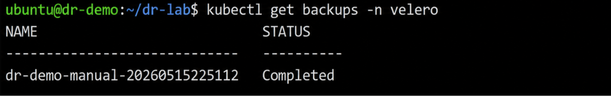
At this point, Kubernetes resources, PersistentVolumeClaims, services, deployments, and PostgreSQL filesystem data were stored in S3-backed backup storage.
Step 4: Simulate a Full Namespace Failure
To simulate a real application outage, the Kubernetes namespace was deleted completely.
./scripts/disaster-simulate.sh namespace
namespace "dr-demo" deleted
This removed:
- PostgreSQL StatefulSets
- PersistentVolumeClaims
- nginx deployments
- Kubernetes services
- namespace-level resources
The environment now reflected a genuine service outage rather than a partial degradation scenario.
Step 5: Restore the Environment from Backup
The latest Velero backup was then restored into the cluster.
./scripts/restore-latest.sh
kubectl get restores -n velero
Once the restore reached Completed status, Kubernetes recreated the workloads and storage resources from backup state. Pods returned to running status without manual intervention:
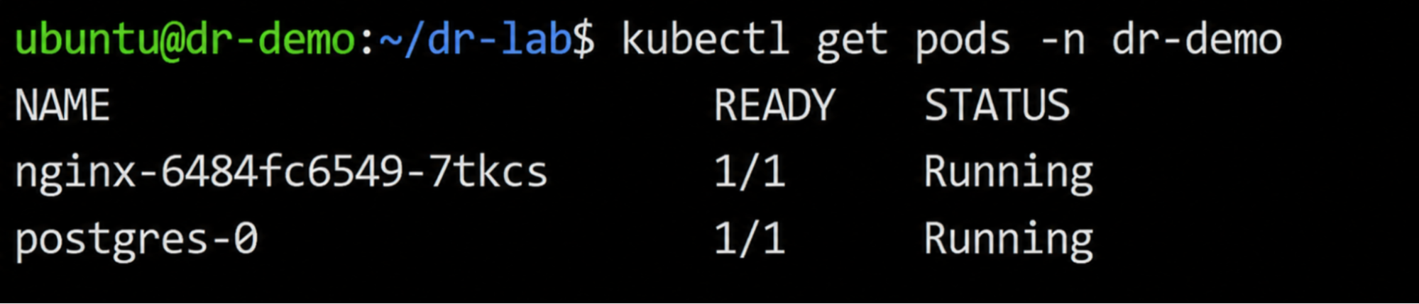
This validated that the restore process successfully recreated both stateless and stateful workloads.
Step 6: Validate Data Integrity and Infrastructure Consistency
Application recovery alone does not confirm recovery correctness. The restored environment must also preserve application state and remain aligned with infrastructure definitions.
The validation script queried the restored PostgreSQL instance:
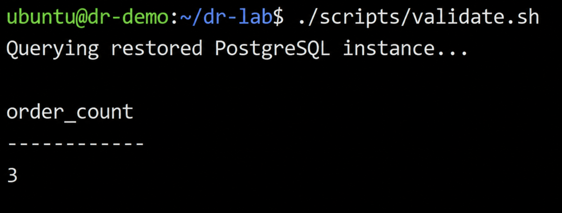
The same records that existed before the outage were restored, confirming that the PostgreSQL data layer recovered successfully.
The application endpoint also resumed serving traffic successfully:
curl -I http://3.238.27.65:30080Finally, Terraform was used to verify that the restored infrastructure still matched the expected IaC definitions:
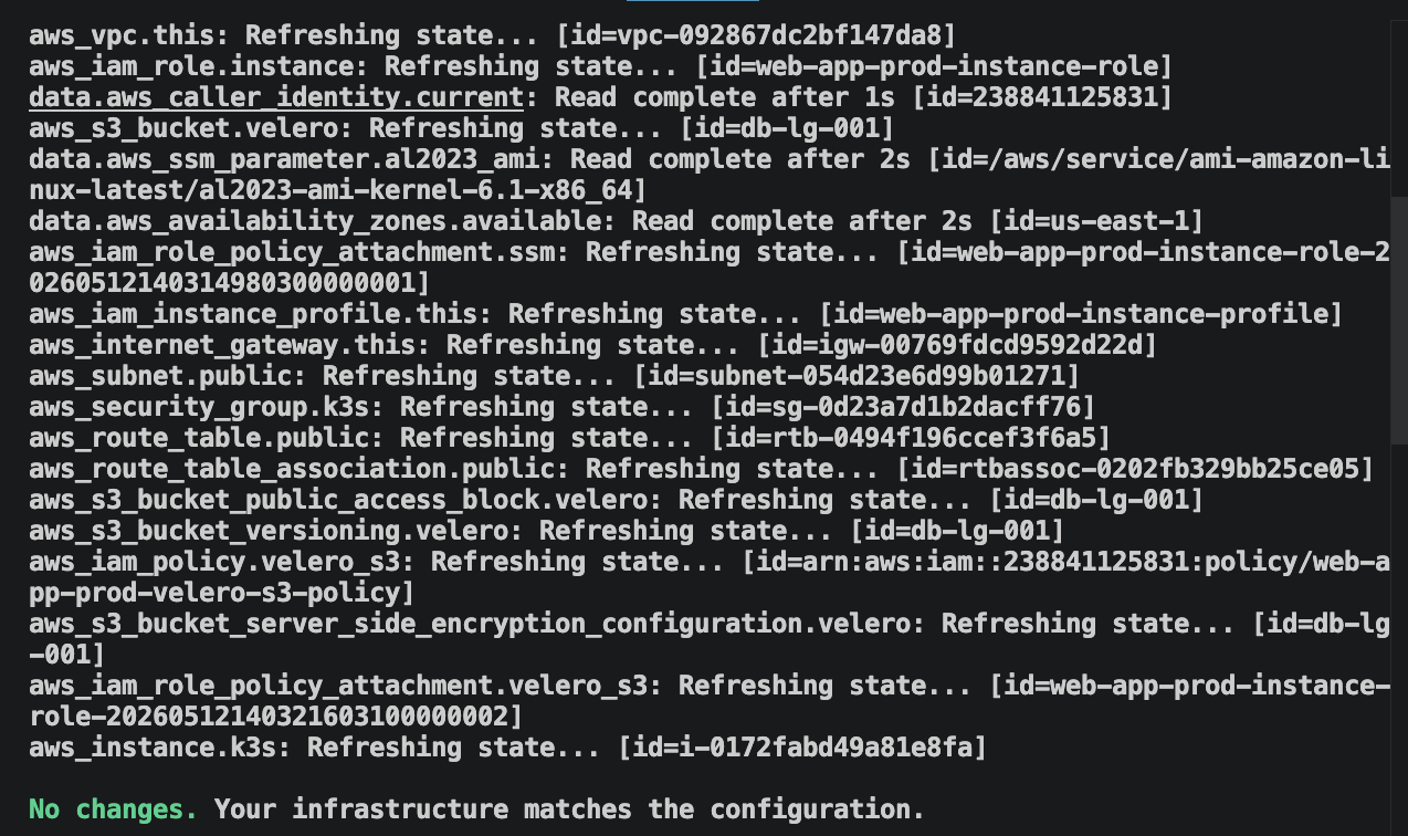
This final step validated that recovery restored not only application functionality, but also infrastructure consistency.
What the Drill Validated
The drill validated the core operational recovery loop: backup, outage simulation, restore, application validation, and infrastructure verification.
What it did not validate were larger-scale recovery concerns such as cross-region failover, multi-account isolation, dependency sequencing across multiple services, or continuous drift management across changing cloud environments.
Those operational challenges become significantly harder as infrastructure scales — especially when production environments evolve continuously outside strict IaC controls. That is where maintaining long-term recovery readiness becomes an infrastructure operations problem rather than simply a backup problem.
Firefly Backup & DR: Keeping Recovery Infrastructure Aligned with Production
A recovery environment that was aligned with production in January will fail in March if the VPC routing rules, IAM policies, or database subnets that changed in between were never replicated to the recovery workspace.
The drill above confirmed that Velero can restore a deleted Kubernetes namespace, its PVCs, and PostgreSQL data to a running state without manual intervention. But the gap between a passing drill and a failed real incident is not backup tooling; it is the production changes that accumulated between the two.
A production VPC receives new routing rules during a migration. A Kubernetes ingress resource is patched manually during an incident. A database subnet changes outside Terraform. An IAM policy evolves to support a new deployment workflow, but the recovery environment never receives the same update.
Production continues operating normally because those changes exist in the live environment. The failure appears during recovery.
The Terraform definitions used to recreate the recovery environment no longer reflect production reality. Infrastructure dependencies required by the application are missing from the restore process. Resources that exist in production were never codified into IaC, so they never become part of the recovery workflow.
That accumulated drift breaks several of the practices covered earlier in this guide:
- Recovery environments should remain reproducible from IaC (Practice 3)
- Infrastructure drift should be detected continuously (Practice 8)
- Unmanaged cloud resources should not exist outside recovery workflows (Practice 3)
- Recovery validation should confirm infrastructure consistency, not only backup completion (Practice 10)
At 10 AWS accounts and 40 services, running terraform plan manually against every recovery workspace after every production merge takes longer than the 24-hour refresh window Practice 8 requires, so drift accumulates undetected. The gap between what Terraform tracks and what actually runs in production is the operational problem Firefly Backup & DR is designed to close.
Where snapshot-only tools restore cloud resources by mutating live infrastructure directly, Firefly generates a Terraform module from the snapshot and opens a pull request; the restore applies through terraform apply, not through console operations.
The workflow starts with Application Backup Policies, where teams define recovery scope using tags such as app=payments, env=production, or tier=critical. Firefly then captures not only the tagged application resources, but also the infrastructure relationships and dependencies required to restore the application correctly, VPCs, subnets, IAM instance profiles, and networking dependencies. Capturing the full dependency graph at backup time, not just the tagged resources, supports Practice 7: when the restore runs, the VPC, subnets, and IAM profiles the application depends on are already included. The Applications Backup & DR dashboard below:
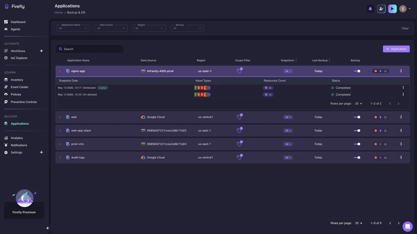
Shows every application with an active backup policy, its snapshot count, last backup timestamp, and source region, so a missing policy shows up as a gap in the list before an incident reveals it. A DR engineer checking the dashboard on Tuesday can see that payments-api has no active backup policy before the Friday drill surfaces it as a missing restore target.
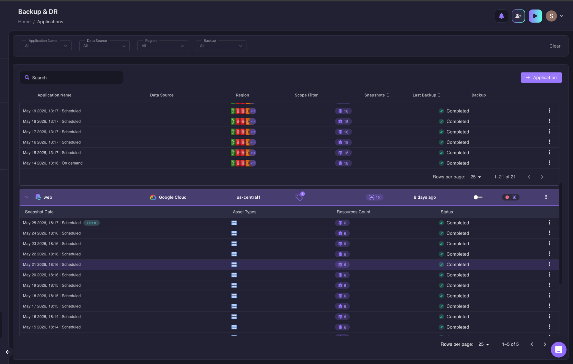
When restoring an application snapshot, teams select recovery points directly from the snapshot inventory and initiate restore workflows from the application scope.
With the Terraform module generated, the restore moves through the team's existing GitOps pipeline rather than requiring direct cloud access during the incident.
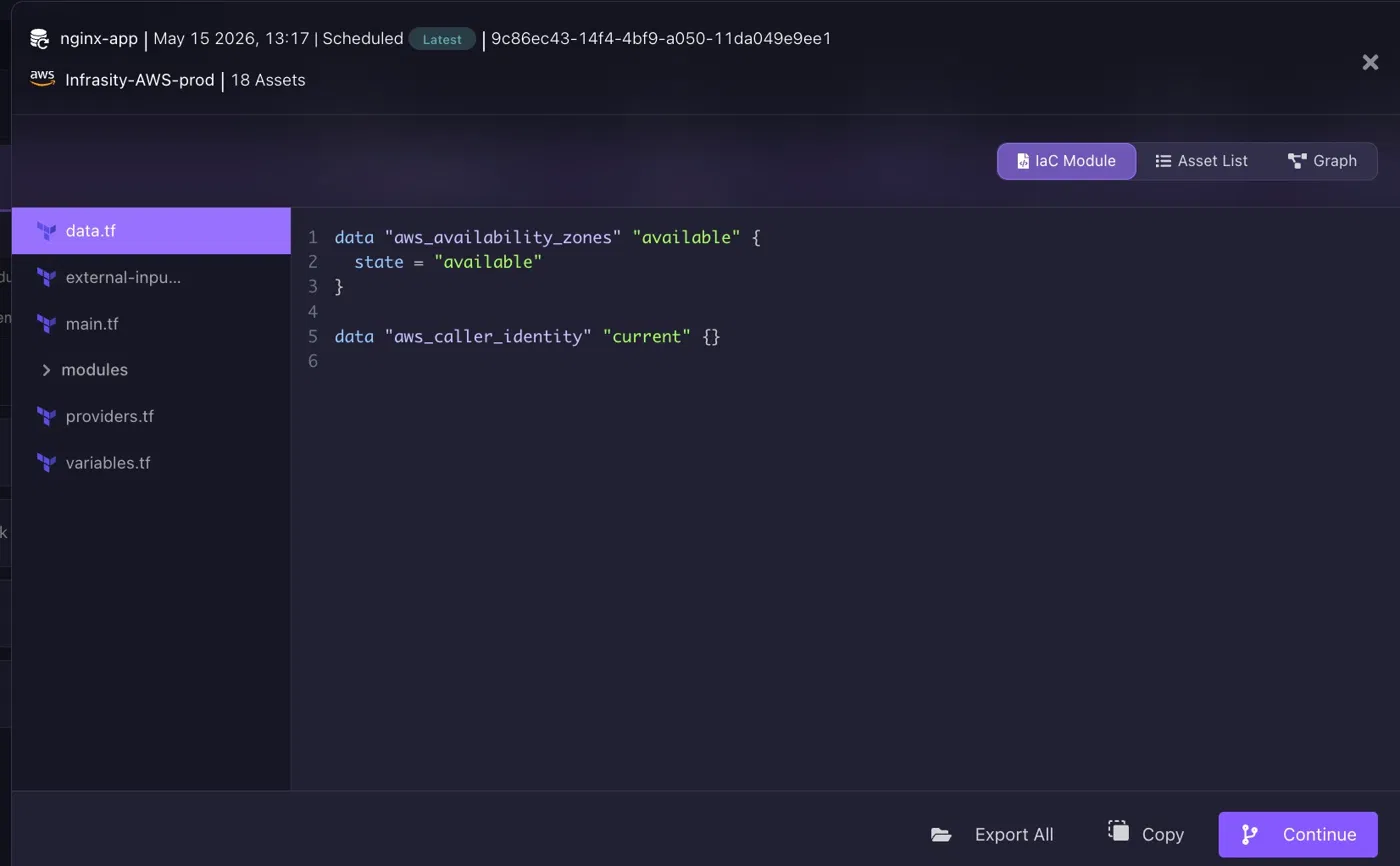
The generated recovery module contains Terraform definitions representing the captured infrastructure state, provider configuration, resource relationships, and dependent infrastructure assets. The restore does not reconstruct infrastructure from memory or console clicks; it applies the same Terraform module that was generated from the last known-good snapshot, keeping recovery aligned with Practice 3.
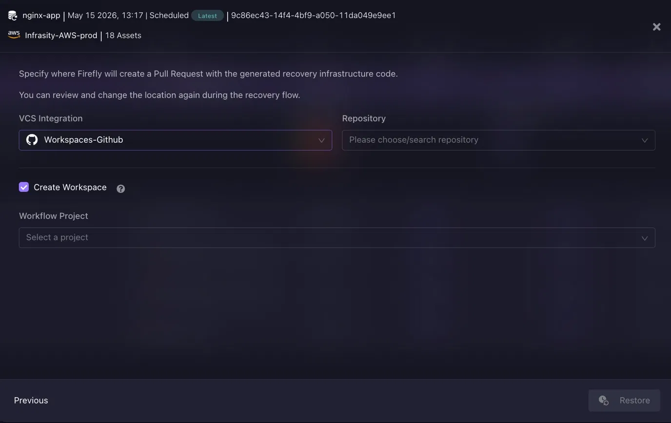
Firefly opens a pull request in the team's GitHub or GitLab repository containing the generated Terraform. The engineer reviews the diff, merges, and the recovery applies through the existing terraform apply workflow. No direct console access, no manual reconstruction, every step in Git history, implementing Practices 4 and 8.
Firefly also continuously monitors cloud infrastructure against Terraform, Pulumi, and CloudFormation definitions to surface unmanaged resources and infrastructure drift before those gaps appear during a real recovery event. For infrastructure originally created outside IaC, Firefly can codify existing cloud resources into Terraform definitions so they become part of the recovery workflow rather than remaining unmanaged dependencies.
Firefly is not replacing Velero or Terraform. Velero handles Kubernetes objects and persistent volume backup. Terraform provisions and manages infrastructure resources. Firefly's role is detecting when production infrastructure changes, a new subnet, a modified security group, or a manually patched ingress rule, have not reached the recovery workspace, and generating the Terraform to close that gap before the next drill.
Conclusion
Cloud disaster recovery is not a backup problem. It is an infrastructure problem, a dependency problem, an automation problem, and a continuous validation problem.
A backup job completing successfully tells a team that data was written to storage. It does not confirm that the network exists to receive traffic, that IAM roles allow the application to read that data, that dependent services are available in the recovery region, or that the Kubernetes manifests still match the production configuration.
Infrastructure and platform teams that treat recovery as an operational engineering discipline, codified in IaC, executed by automation, tested on a schedule, and measured as a continuous metric, build the kind of recovery capability that holds under real failure conditions. Teams that treat it as a backup schedule discover the gap when it is most expensive to close.
The practices in this guide are not new. Most teams know them. The failure mode is not ignorance of the practices; it is treating them as aspirational rather than operational. Define the tiers. Write the IaC. Automate the failover. Run the drills. Measure the results. That sequence, repeated consistently, is what recovery readiness actually looks like.
FAQs
What are cloud best practices?
Cloud best practices are a set of guidelines used to build secure, scalable, reliable, and cost-efficient cloud environments. They typically include infrastructure automation, regular backups, disaster recovery planning, monitoring, identity and access management, and resource optimization. Following these practices helps organizations improve availability, reduce downtime, and maintain operational resilience.
What are the 4 stages of disaster recovery?
The four common stages of disaster recovery are assessment, planning, implementation, and recovery/testing. Assessment identifies risks and critical systems, while planning defines recovery procedures and objectives like RTO and RPO. Implementation sets up backup and recovery mechanisms, and recovery/testing validates that systems and data can be restored successfully during an outage or disaster.
How to test DR on AWS?
Disaster recovery testing on AWS typically involves simulating failures and validating whether applications, databases, and infrastructure can be restored within defined recovery objectives. Teams commonly test backup restoration, failover procedures, infrastructure recreation using IaC tools, and application functionality after recovery. Regular DR drills help identify gaps in automation, backup integrity, and operational readiness.
How do you handle disaster recovery in a cloud environment?
Disaster recovery in a cloud environment is handled through automated backups, multi-region or multi-zone deployments, infrastructure as code, and continuous monitoring. Organizations use replication, snapshot-based recovery, and orchestration tools to restore workloads quickly during outages. A strong cloud DR strategy also includes regular testing, defined RTO/RPO targets, and documented recovery workflows to minimize downtime and data loss.

.avif)
.avif)


.webp)


.webp)


